Lexus SC300 / Lexus SC400. Manual - part 517


  Index      Lexus     Lexus SC300 / Lexus SC400 - service repair manual


Search            


Content   ..  515  516  517  518   ..


Lexus SC300 / Lexus SC400. Manual - part 517


INSPECTION OF INJECTORS

1. INSPECT 

INJECTOR 

INJECTION

CAUTION: Keep injector clear of sparks during the test.

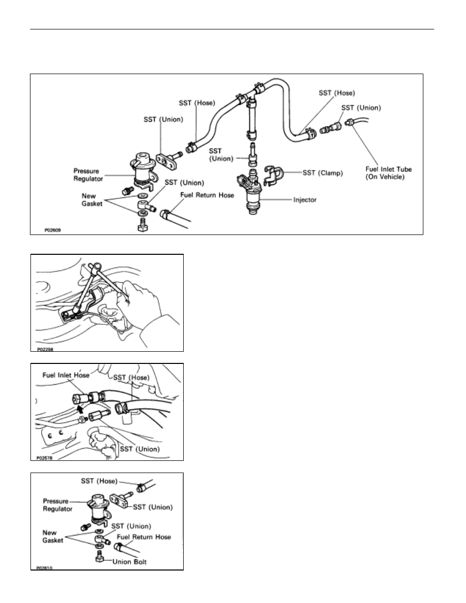
(a)  Remove the two bolts and fuel hose clamp.

(b)  Disconnect the fuel inlet hose from the fuel tube.
(c)  Connect SST (hose) to the fuel inlet tube with SST

(union). Tighten the flare nut on the fuel tube.

SST 09268–41045 (90405–52010)

Torque:     30 N

m (310 kgf

cm, 22 ft

lbf)

HINT: Use SST. (See page 

FI–14

)

SST 09631–22020

(d)  Install a new O–ring to the fuel inlet of the pressure

regulator.

(e)  Connect SST (hose) to the fuel inlet of the pressure

regulator with SST (union) and the two bolts.

SST 09268–41045 (09268–41090)
(f)  Connect the fuel return hose to the fuel outlet of the

pressure regulator with SST (union), two new gaskets
and union bolt.

SST 09268–41045 (90405–09015)

FI–30

EFI SYSTEM

Fuel System (Injectors)

(g)  Install the grommet and a new O–ring to the injector.
(h)  Connect SST (hose) to the injector with SST (union),

and hold the injector and union with SST (clamp).

SST 09268–41045
(i) 

Put the injector into the graduated cylinder.

HINT: Install a suitable vinyl hose onto the injector to prevent
gasoline from splashing out.

(j) 

Using SST, connect terminals +B and FP of the check
(”DIAGNOSIS”) connector.

SST 09843–18020
(k)  Reconnect the cable to negative (–) terminal of battery.
(l) 

Turn the ignition switch ON.

NOTICE: Do not start the engine.

(m)  Connect SST (wire) to the injector and battery for 15

seconds, and measure the injection volume with a
graduated cylinder. Test each injector two or three
times.

SST 09842–30070

Volume:     70–88 cm

3

 (4.3–5.4 cu in.) per 15 sec.

Difference between each injector:

          9 cm

3

 (0.5 cu in.) or less

If the injection volume is not as specified, replace the injector.

2. INSPECT 

LEAKAGE

(a)  In the condition above, disconnect the test probes of

SST (wire) from the battery and check the fuel leakage
from the injector.

SST 09842–30070

Fuel drop:     One drop or less per minute

(b)  Disconnect the battery negative (–) cable.
(c) Remove 

SST.

SST 09268–41045 and 09843–18020

(d)  Reconnect the fuel inlet hose to the fuel tube.
SST 09631–22020

Torque:     30 N

m (310 kgf

cm, 22 ft

lbf)

HINT: Use a torque wrench with a fulcrum length of 30 cm
(11.81 in.).

EFI SYSTEM

Fuel System (Injectors)

FI–31

(e)  Install the fuel hose clamp with the two bolts.

INSTALLATION OF INJECTORS

(See Components on page 

FI–27

)

1. 

INSTALL INJECTORS AND DELIVERY PIPE
(a)  Install the grommet to each injector.
(b)  Apply a light coat of gasoline to a new O–ring and install

it to each injector.

(c) While  turning  the  injector  clockwise  and

counterclockwise, push it to the delivery pipe. Install the
six injectors.

(d)  Position the injector connector outward.

(e)  Place the six insulators and three spacers in position on

the intake manifold.

(f) 

Place the six injectors together with the delivery pipe in
position on the cylinder head.

FI–32

EFI SYSTEM

Fuel System (Injectors)

(g)  Temporarily install the three bolts holding the delivery

pipe to the cylinder head.

(h)  Check that the injectors rotate smoothly.
HINT: If injectors do not rotate smoothly, the probable cause
is incorrect installation of O–rings. Replace the O–rings.
(i) 

Position the injector connector upward.

(j) 

Tighten the three bolts holding the delivery pipes to the
intake manifold.

Torque:     21 N

m (210 kgf

cm, 15 ft

lbf)

2. 

INSTALL CONTROL VALVE ACTUATOR
(a)  Install the actuator with the two bolts.

Torque:     6.8 N

m (70 kgf

cm, 61 in.

lbf)

(b)  Inspect the IACV. (See page 

FI–59

)

3. CONNECT 

INJECTOR 

CONNECTORS

HINT: The No. 1, No. 3 and No. 5 injector connectors are gray,
and the No. 2, No. 4 and No. 6 injector connectors are dark
gray.

4. 

CONNECT VACUUM SENSING HOSE

EFI SYSTEM

Fuel System (Injectors)

FI–33


Content   ..  515  516  517  518   ..